Enabling the New USB 3.0 Type-C Connector in Designs
August 19, 2015, Intel Developer Forum, San Francisco—Brad Saunders, architect/strategist, Bob Dunstan, principal engineer, and Rahman Issmail, USB senior architect at Intel presented design considerations and implementation details for the new Type C connector for the USB. The latest releases for USB enable greater connectivity to other protocols and provide power delivery.
Currently, USB is used for connecting a host device to multiple types of peripherals such as human interface devices, displays, storage, and networks. As notebooks get thinner, available space for the multitude of connectors is becoming scarce, so an emerging model is to have the main platform connect to all peripherals through a hub. The latest revision of the USB spec also include power delivery to or from any device.
The latest spec, branded Superspeed USB, is capable of transfers at rates up to 10 Gbps. This speed allows more high-performance peripherals like multiple displays, display resolution greater than 1080p, and high-speed data storage. it is possible to connect AV, webcam, storage, etc. over a single connection through a hub. The 3.1 release adds a security protocol for authenticating hosts, devices, cables, and power sources, and updates the audio device class.
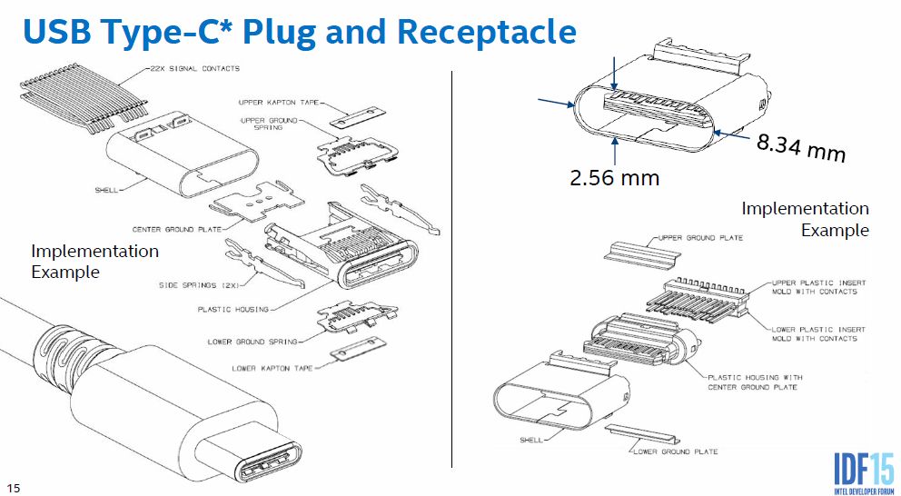
The biggest change is the new connector. This new connector is a new design that is tailored to the small, thin hosts devices and is similar in size to the Micro-B connector seen on phones and tablets. The new connector allows reversible plug and cable orientation and supports scalable power charging. See figure 1.

Figure 1: The new connector mechanical drawing shows the many differences from the current connectors.
Some of the functional highlights for the USB Type-C*include:
Flipping and swapping, so both plug and cable orientation no longer keyed, which requires new pins enable plug orientation flipping and a path for future upgrades. Now the hosts and devices require logic to resolve their roles for proper USB bus operation.
The active cables need two power sources, one for the VBUS with an expanded definition with USB Type-C Current, and VCONN for the dedicated source for powering cable electronics.
Functional extensions for the interface include alternate and accessory modes, and functional support for identifying and managing passive and active cables. The standard now includes two Type C to C connectors. The first is for superspeed USB and uses all 15 lines in the new connector. The other is for USB 2.0 functions and uses a minimum of 5 wires. Other cable combinations are A to C for new devices to legacy hosts, and C to B and C to micro-B for legacy peripherals to new hosts. Adapters are defined for C to micro-B and C to A. all of the standard cables should be capable of handling u to 3 A at 5 V for charging.
As a result of the many changes, separation of the lows speed signaling for handshakes, configuration, and power need to be carefully designed. The high-speed lines need to be shielded both in the cable and on the board. The pin-out is shown in figure 2.

Figure 2: The Type-C functional pin-out shows the high-speed signals towards the ends and the power and configuration lines in the center of the connector.

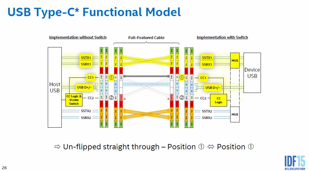
The functional model for the differs depending on implementation with or without a switch. See figure 3. Because the cable is not keyed, there a many possible orientations for the board and cable connectors, which is automatically resolved by the active cable logic.

Figure 3: The functional model shows direct (1-1) connections through a cable. Other modes like 1-2, 2-1, 2-2 call for different configurations.
The ports have many possible behaviors. For data, a USB port can be downstream facing (DFP) like current Type A host or hub ports, or upstream facing (UFP) like standard Type B or Micro-B ports. The ports can source or sink power in any configuration. Type –C ports can be host-mode only, device-mode only or dual role (DRP). a DRP transitions between source and sink during the initial handshake at attach, default is power sources behave as a DFP and sink as UFP, but the configuration can be dynamically swapped.
The signal and power configuration has to be resolved upon initial attach, so the host needs to know if the cables or connectors are flipped and if any peripheral is connected. This information is the function of the CC pins. The host has to detect cables and peripherals, then set switches to connect power to the VBUS and signaling voltages to the CC lines. The device has to detect current flow from CC1 and 2 to detect a connection. A DRP is more complex, since it has to perform both host and device functional identification. The cables need to be marked electronically to indicate power delivery capability of the standard 3 A or high power of 5 A at 20 V. The cable has a max limit of 70 mW from the VCONN line.
Alternate modes for the ports and connectors include a Display Port alternate mode with signaling specifications from VESA, and a MHL alternate mode from the MHL consortium. The new interconnects have a procedure to identify incompatible connections. This interface shows up on the device’s USB 2.0 bus when alternate modea are unable to be negotiated.
Power delivery is another negotiated process. Voltage and current capabilities for power delivery up to 100 W is negotiated over the power pins. The limits include cable current capacity as well as international safety limits. The power source can be in any device and is independent of cable orientation. The source can be dynamically changed during operation. In the Type –C connector, the power delivery signaling is separate from the power line, while in the older connectors it is on a common line. the power delivery has multi-drop capabilities for electronically marked active cables.
The negotiations for data and power delivery require greater complexity and functionality in new hosts to accommodate the legacy devices. Communications for power delivery are port to port with no dependence on SB communications. The handshakes include cable capability, voltage, current , and direction. All of the parameters can be renegotiated on the fly to share, reverse, and increase or reduce power. The data are packetized and transferred across all connected components.
The signaling for power delivery requires a new set of instructions for the USB and has standard and vendor-specific modes and policies. Passive cables by definition are unmarked, and will default to basic settings. Active cables are marked with signal conditioning circuits and are addressed by the DFP for power management.
Some issues that have been identified in workshops include the following:
All 4 of the high-speed wires can be used simultaneously, but be careful of design and layout of the paddle board in the connector.
Don’t rely on VCONN as it may not be in every Type-C connector and port.
Use the CC line to signal connect. USB Type –C ports are cold sockets until connect is detected. This may mean that just plugging in an active cable may need consideration.
Use only legacy Rp in Type-C to Type-A cables.
For power delivery the issues so far include:
When coming to a workshop with a battery-operated device, bring fully discharged batteries.
Pass though power budgeting has to account for power losses and power consumption in the pass-through devices, and a standard Type-A port draws power with nothing connected.
Implement billboard, the unable to negotiate signaling.
Test with as many vendors as possible.
The new USB standard will require new compliance requirements for all the system components; cables, connectors, links, frameworks, hub, power supply, PHY, protocol and policy for power and data delivery. The USB organization has compliance test tools and procedures to validate the hardware and software and hosts plugfests and workshops. See http://www.usb.org/developers/compliance/ssusb_testing/ for more details on compliance testing. Other information and specifications are available at www.usb.org.